











Star shaped unloader: Installation, commissioning, sealing and operation inspection guide
Jan 24,2026

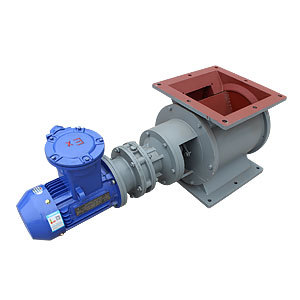
Star shaped unloader (also known as star shaped unloader valve or rotary feeder) is a core auxiliary equipment of industrial dust removal system and powder conveying system, mainly responsible for air locking unloading and quantitative feeding functions. Its installation accuracy, commissioning quality, and sealing directly affect the negative pressure stability, unloading efficiency, and energy consumption of the system. This article provides a detailed overview of the installation and commissioning process, sealing testing methods, and operational inspection points of star shaped unloaders from a practical perspective, providing technical references for overseas on-site operations and maintenance.
1、 Pre installation preparation and basic requirements
The preparation work before installation should take into account equipment protection, on-site adaptability, and operational safety to avoid installation deviations or operational failures in the later stage.
(1) Pre inspection
1. Equipment appearance inspection: Confirm that the main body of the star shaped unloader is not damaged during transportation, and that the shell, impeller, transmission shaft, motor, and reducer are not deformed, cracked, or have missing components; Check if the connecting components (bolts, nuts, gaskets) and sealing components (packing, sealing rings) are complete and meet the equipment assembly standards.
2. On site adaptation confirmation: Check the spatial dimensions and load-bearing capacity of the installation location to ensure that the connection dimensions of the equipment with the loading and unloading pipes and flanges match; Check that the on-site power parameters (voltage, frequency) are consistent with the motor nameplate, and that the wiring ports are not damaged or oxidized.
3. Preparation of tools and accessories: Prepare torque wrench, level gauge, plug gauge, sealant, and lubricating grease.
(2) Basic installation specifications
1. Positioning and fixing: Place the unloader on a preset foundation and calibrate the equipment's levelness with a spirit level to avoid impeller jamming and uneven bearing force on the shaft caused by tilting. After calibration is completed, tighten the base with expansion bolts and tighten the bolts to the required torque according to the equipment manual to ensure no displacement during operation.
2. Flange connection: When the upper and lower feeding pipes are connected to the flange of the unloader, sealant should be evenly applied to the flange surface, sealing gaskets should be placed, and bolts should be symmetrically and cross tightened to ensure that the flange surface is tightly fitted without gaps. It is forbidden to forcefully connect the flange to avoid deformation of the shell affecting the operation of the impeller.
3. Transmission system installation: If the motor and reducer are separated, the coaxiality between the motor output shaft and the reducer input shaft needs to be calibrated, with a radial runout of ≤ 0.1mm and a controlled end face clearance of 2-3mm. When connecting the coupling, bolts should be uniformly tightened around the entire circumference and protective covers should be installed to prevent safety accidents during operation.
4. Wiring specifications: Connect the power cord according to the motor wiring diagram, perform grounding treatment, and avoid static electricity accumulation or leakage; After the wiring is completed, rotate the coupling by hand to confirm that the impeller is not stuck, and then test the motor direction by powering on.
2、 Debugging process and key operational points
Debugging is carried out in two steps: no-load debugging and load debugging. The core is to verify the stability of equipment operation, parameter adaptability, and identify potential faults.
(1) No load debugging
1. No load start: Connect the power supply, start the unloader, run it without load for 30-60 minutes, and observe the operation status of the equipment. Key inspection: The motor and reducer have no abnormal noise, and the bearing temperature rise is ≤ 40 ℃; The impeller runs smoothly without any jamming or impact sound, and the coupling does not shake.
2. Gap adjustment: If there is abnormal noise caused by friction between the impeller and the shell, measure the radial gap and end face gap between the impeller and the shell with a feeler gauge after stopping the machine. If the gap is too small, loosen the base bolts and fine tune the equipment position; Excessive clearance may affect the sealing performance, and the impeller or housing needs to be replaced.
3. Lubrication inspection: Observe the lubricating oil level of the gearbox during operation to ensure that the oil level is between the upper and lower limits of the oil gauge and there is no leakage; Regularly add lubricating grease to the bearing end, with a recommended amount to fill 1/2-2/3 of the bearing chamber each time, to avoid excessive lubrication and excessive temperature rise.
(2) Load debugging
1. Progressive loading: After passing the no-load debugging, start the upstream powder conveying or dust removal system, gradually increase the discharge volume, and avoid instantaneous full load operation. During the loading process, monitor the changes in motor current to ensure that the current remains stable within the rated current range and there is no overload phenomenon.
2. Unloading efficiency verification: According to the working conditions, measure the unloading amount per unit time, compare it with the rated unloading amount of the equipment, and control the deviation within ± 5%. If the unloading volume is insufficient, check whether the impeller has accumulated material, whether the feeding pipe is blocked, or adjust the equipment speed; If there is excessive unloading, it is necessary to optimize the feeding control or adjust the speed.
3. System compatibility check: During load operation, observe the negative pressure stability of the upstream dust collector or silo. If there is no obvious negative pressure fluctuation, it indicates that the air lock function of the unloader is normal and has not affected the overall operation of the system.
3、 Sealing testing methods and optimization measures
The sealing performance of the star shaped unloader is directly related to the air locking effect - seal failure can cause external air to infiltrate the system, reduce dust removal efficiency, increase energy consumption, and may also result in dust leakage and environmental pollution. Sealing testing needs to focus on three core areas: shaft end sealing, flange sealing, and impeller clearance.
(1) Sealing part inspection
1. Flange sealing test: During load operation, apply a smoke detector or soapy water to the flange connection to observe whether there is smoke infiltration or bubble generation. If there is no obvious leakage, it is considered qualified. If there is a leak, tighten the bolts after stopping the machine. If the leak still occurs, replace the sealing gasket and reapply the sealant.
2. Shaft end sealing detection: The shaft end is a dynamic sealing part and a high leakage point. During operation, observe whether there is dust overflow from the shaft end, or use white paper to approach the shaft end. If there is no dust adhesion, it is considered qualified. The commonly used forms of shaft end seals are packing seals or mechanical seals, which require targeted inspection:
(1) Packing seal: If the leakage is small, evenly tighten the packing gland bolts; If the leakage is large, the packing needs to be replaced.
(2) Mechanical seal: If leakage occurs, it is mostly due to wear and deformation of the sealing surface or aging of the sealing ring. The shaft end needs to be disassembled and the mechanical seal component needs to be replaced. During installation, ensure that the sealing surface is clean, free of impurities, and tightly fitted.
3. Inspection of impeller clearance seal: Excessive clearance between the impeller and the shell can easily cause air lock failure, which can be verified through negative pressure testing: close the feeding port of the unloader, open the upstream system to create a negative pressure of -500Pa inside, and after closing the system, observe the decay rate of the negative pressure value. If the decay is ≤ 100Pa within 5 minutes, it is considered qualified. If the attenuation is too fast, it is necessary to adjust the impeller clearance or replace worn parts.
(2) Sealing optimization measures
1. Suitable sealing components for working conditions: For high temperature and corrosive dust working conditions, sealing components made of high temperature and corrosion-resistant materials should be selected to avoid aging and failure of the sealing components; Flammable and explosive dust conditions require sealing components with anti-static properties, while strengthening shaft end sealing to prevent dust leakage and safety risks.
2. Regular maintenance of sealing parts: Establish a seal maintenance ledger, check the packing seal every 3-6 months, and check the mechanical seal every 6-12 months, and replace aging and worn parts in a timely manner; Clean the sealing surface and apply special lubricating grease during each shutdown maintenance to improve the sealing effect.
4、 Operation inspection and troubleshooting
Daily operation inspections should be carried out regularly to promptly detect and handle abnormalities, extend the service life of equipment, and avoid system shutdown. Inspection is divided into daily inspections and regular comprehensive inspections.
(1) Daily inspection points (1-2 times a day)
1. Operating status: Observe whether the equipment is running smoothly, without any jamming, impact, or abnormal noise; The temperature rise of the motor and reducer is normal, and there is no burning sensation.
2. Sealing condition: Check whether there is dust leakage at the shaft end and flange. If there is no leakage, it is qualified.
3. Lubrication status: The reducer has no oil leakage and the oil level is normal; There is no dry grinding noise at the bearing end, and the lubricating grease is sufficient.
4. Electrical system: The motor current is stable, the wiring terminals are not overheating or loose, and the frequency converter is running normally (frequency converter version).
(2) Regular comprehensive inspection (once a month)
1. Mechanical components: Remove the coupling guard and check if the coupling bolts are tightened and worn; Measure the clearance between the impeller and the shell to ensure it is within the standard range; Check the wear of the bearings and ensure there is no jamming or abnormal noise during rotation. Otherwise, replace the bearings.
2. Transmission system: Check the quality of the gearbox gear oil. If the oil turns black or contains impurities, it should be replaced in a timely manner; Add lubricating grease to the motor bearings and tighten the wiring bolts.
3. Sealing components: Conduct a comprehensive inspection of the shaft end seal and flange seal, replace aging seals, and reapply sealant.
(3) Common troubleshooting and handling
1. Operation stuttering and abnormal noise: The reasons are mostly due to material accumulation in the impeller, bearing wear, and friction between the impeller and the housing. Solution: Stop the machine and clean the accumulated material on the impeller; Check the bearings and replace them if they are worn out; Adjust the impeller clearance to eliminate friction.
2. Motor overload: Causes include excessive discharge volume, impeller jamming, and motor failure. Solution: Reduce the amount of discharge and clean up any debris stuck in the impeller; Check the motor winding and bearings, and eliminate any faults in the motor itself.
3. Sealing failure and dust leakage: locate the leakage location according to the previous sealing detection method, tighten bolts, replace seals, or adjust impeller clearance.
4. Decreased unloading efficiency: reasons include impeller wear, blockage of feed pipe, and abnormal speed. Solution: Replace the worn impeller; Clean the feeding pipe; Check the speed of the frequency converter or motor and adjust it to the rated speed.
5、 Precautions for safe operation
1. During installation, debugging, and maintenance, the power must be cut off and a "Do Not Close" sign must be hung to avoid accidental start-up and safety accidents.
2. During load operation, it is prohibited to remove the protective cover or touch rotating parts (couplings, impellers) to prevent mechanical injury.
3. In the case of flammable and explosive dust conditions, the equipment needs to be properly grounded to prevent static electricity, and the grounding resistance should be regularly tested to avoid static electricity accumulation and explosion.
4. Under high temperature conditions, wait for the equipment to cool down to room temperature before conducting maintenance to prevent burns.
The installation, debugging, sealing control, and operation inspection of star shaped unloaders are centered on "standardized operation, precise adaptation, and regular maintenance". It is necessary to optimize the installation and sealing plan based on specific working conditions (temperature, dust characteristics, discharge volume), establish a regular inspection and maintenance mechanism, which can ensure the stable operation of equipment, improve the overall efficiency of the system, and reduce operation and maintenance costs. In practical operation, it is necessary to strictly follow the requirements of the equipment manual, flexibly adjust the operating points according to the special needs of different working conditions overseas, and ensure the adaptability and safety of the equipment.
Hot Tags:
PREVIOUS:


Contact Us
Tel:
WeChat:
WhatsApp:
E-mail:
Address:
338 National Road South, Longfengdian Village, Botou City, Hebei Province, China
JiuznTomine is expertly delivering technically complicated projects in markets & provides custom solutions for their customized need.


CONTACT INFO
Tel: +86 18531710311
WeChat: +86-18531710311
338 National Road South, Longfengdian Village, Botou City, Hebei Province, China